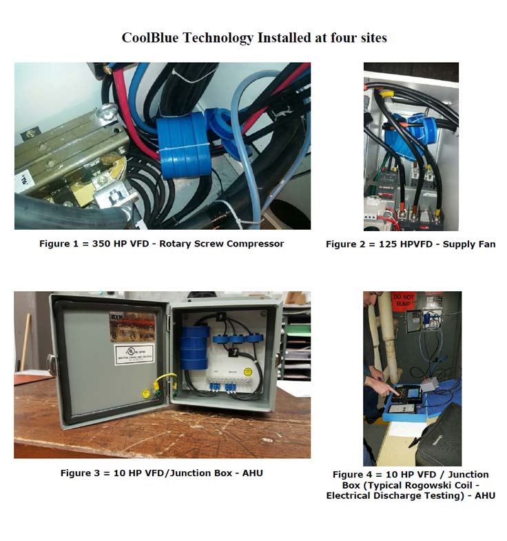
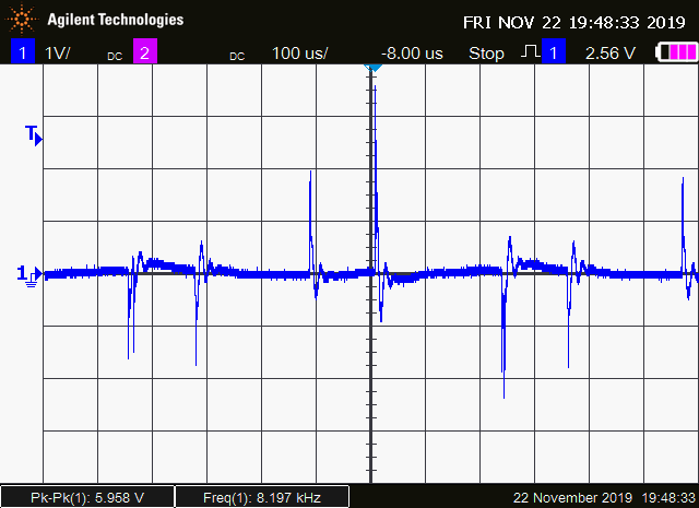
Electrical discharge levels seen on an Oscilloscope using Rogowski Coil
helps determine potential shaft current issues
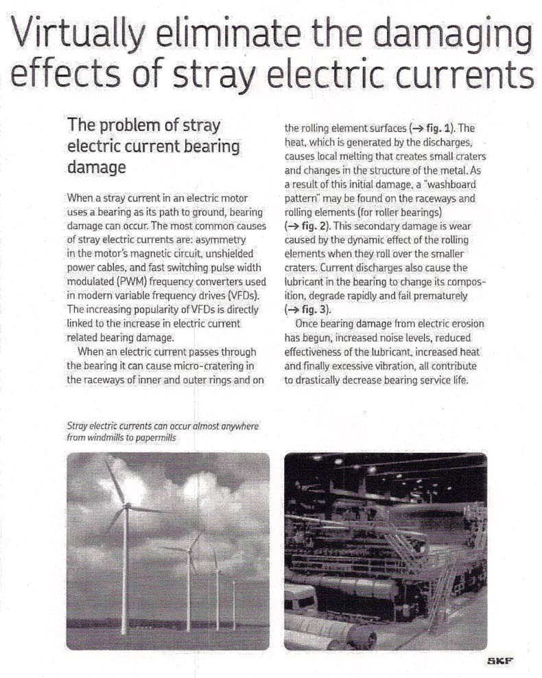
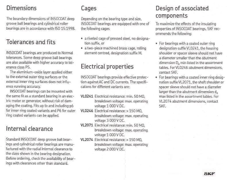
This article contains information about, and offers explanations for, the electrical phenomenon that causes motor bearing defects due to micro-arcing (also referred to as shaft currents). Shaft currents leads to Electrically Induced Bearing Damage (EIBD) and has been found on 600V and 460V VFD applications. EIBD has been confirmed using vibration analysis, metallurgical testing and electrical engineering studies. EIBD is not present everywhere and on all motors; but the potential exists, and it has been found at numerous locations from 1992 to last night on a motor bearing replacement project.
Original article: 2002 with revisions up to 2022
Article by: Garrett Sandwell, MET, CVA, ASNT 3, VIBES Corp
Download the PDF if you want to print or save this article (11 MB)
Preface
The purpose of this report is to provide the reader with an introductory knowledge of the phenomenon of Electrically Induced Bearing Damage (coined "EIBD" from 1992) also known as Shaft Currents, and/or Electrical Discharge Machining, which situations it occurs, how to identify it, and how to remedy the problem. VIBES Corp have repaired, replaced, and analyzed various bearings used in numerous VFD applications and in motors from 5 HP to 350 HP. The problem started showing up in about 1992 (or earlier) and is still present in 2020. This major problem pertained to rapid defects in motor bearings that suddenly developed very loud noise and erratic vibration acceleration spectrum data necessitating immediate solutions and further studies.
Solutions and studies to answer these questions:
- Why this happened so quickly on any VFD applications.
- How to prevent the problem from reoccurring once new bearings are replaced.
- How to prevent the problem on new VFD installations.
This report is meant to provide the reader with accurate facts and knowledge on EIBD so that you can solve problems on your own or have VIBES Corp assist.
Summary
EIBD (Electrically Induced Bearing Damage) is the result of an induced voltage in the rotor and shaft of a motor. The IGBT's (Insulated Gate Bipolar Transistors) used in some PWM (Pulse Width Modulation) and VF (Variable Frequency) drives act as high frequency switches. Their switching can cause bearing discharge current which, when coupled with the fast rise times of the IGBT inverter output, causes an induced voltage in a motor's rotor. Bearing grease has a certain dielectric strength to it, but when the voltage induced in the rotor capacitive couples to the shaft, it may exceed this strength and then current flows from the shaft through the lubricated bearing into the motor frame. The current causes arcing through the lubricant, which results in pitting on the bearings and fluting on the bearing races, leading to premature failure of the complete bearings. All it takes is a shaft voltage of 6V to cause arcing through a bearing lubricant, and in some (lab experiments) cases with VFD's, voltage peaks have been seen to reach 70 to 370V on the shaft, clearly above any acceptable level. A conductive coupling between the driven and drive shaft can result in damage to the driven equipment's bearings as well. Recommendations for this problem in most economical order are, firstly, to use electro conductive grease in sealed bearings, which acts as a partial insulator and will help re-direct a percentage of the induced current from conducting through the bearing. Electro conductive grease inside sealed ball bearings has proven to avoid EIBD problems for over 5 years and on motors ranging from 10 HP to 125 HP. After 5 years or more and/or depending on vibration and noise analysis the process of having to replace the motor bearings with electro conductive grease would be repeated.
Installing a shaft grounding system can also be considered. The rotor grounding seals or brushes come in two arrangements. The first is external and the other is internal. The rotor grounding seals require machining (internal) or drill and tapping (external) for the assembly to accurately fit onto the shaft and are typically mounted on the drive end bell of a motor. In some cases both ends of the motor shaft are grounded using the seals. The rotor grounding seals and brushes have carbon fibres that contact the shaft and create a path to take the micro electrical current back to the stator – avoiding the path through the ball bearings.
In two of the most unusual cases of serious EIBD ever discovered by this writer, the problem required an electrical engineering study that recommended the installation of Inversine Advanced Universal Sinewave Filter (AUSF). See sections of one study completed by Tony Hoevenaars, P. Eng. Mirus International under the header "Resolving Inverter Driven Motor Issues".
Introduction
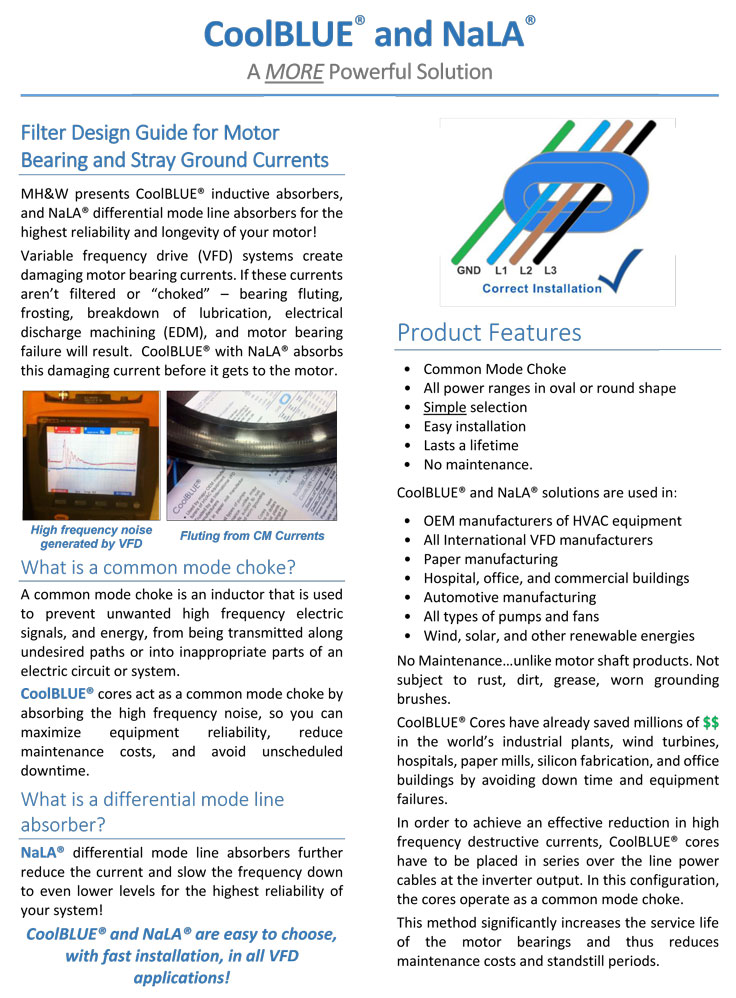
Electrically Induced Bearing Damage (EIBD) is a widespread problem that has been overlooked and/or avoided since 1992. The reason the word "avoided" has been used is due to the unknown issue regarding whether or not EIBD was a motor or VFD manufacturer warranty problem. In the end the client usually accepts the problem and costs to resolve EIBD. Therefore, another reason for writing this article is to make the end users aware of the issue so they can take the necessary steps or ask questions related to avoiding EIBD at the design or installation stage of a VFD retrofit or newer projects. Over the last few years some VFD manufacturers are installing protective parts to avoid EIBD but as an optional cost. See information "Cool Blue Inductive Absorbers" here.
EIBD has been found on 600 and 460 V and possibly higher service voltages.
Regardless of the make or model of the motor or variable frequency drive equipment studies have proven that EIBD can occur within one week, six months or longer from the day of repairs or new start up. The extent of motor bearing electrical damage on many motors and at numerous locations resulted in rapidly increasing noise levels and erratic high frequency acceleration vibration spectrum data. In all studies done to date the bearing defects are similar as follows: bearing balls are frosted or dull grey in appearance; raceways have deep, irregular wear all around (fluting); and grease may be discoloured and have a burned odour.
Metallurgical studies called SEM (scanning electron microscope) have also been completed on several bearings that were found with EIBD defects. See SEM photos further down on this page (Figures 6 and 7).
Variable Frequency Drives - VFD/AFD/VSD
To understand Electrically Induced Bearing Damage, a good understanding of VFD's (Variable Frequency Drives) must first be attained. When VFD's started to become popular (since the late 80's) one of the major issues was shaft current. For quite a while the problem was treated in the usual manner: insulating the motor ODE (Opposite Drive End) bearing, or adding a grounding brush on the motor drive end (DE) Driven end. The problem was that each of these proven solutions yielded mixed results. Many people disagreed on which solution was the best and many reported less-than-satisfactory results with either method. Higher switching frequencies of around 20 kHz caused more bearing problems than slower drive settings of around 5 kHz but there is no clear line above which problems are expected. The VFD works by rectifying AC (Alternating Current) to DC (Direct Current), and chopping the DC into positive and negative pulses to simulate an AC sine wave. Varying the DC pulse width simulates a variable AC sine wave and changes the frequency, thereby changing the motor speed. One problem with that is the common voltage (the voltage common to both input terminals of a device). When a 3-phase motor operates from a true sine wave, the common mode voltage is always zero, but with the VFD, the balance no longer exists.
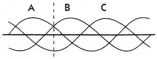
Figure 1: 3 phases 120 degrees apart from each other
Draw a vertical line (that's a point in time) at any point on the graph. Sum the voltages (above the horizontal axis is positive, below is negative), and the common mode voltage is always zero.
DC is either positive or negative, so at any point in time the three phases are either plus, plus, minus or plus, minus, minus. Common mode voltage is essentially line voltage, which, if not zero, as in the three-phase motor case, induces a current on the motor shaft. With the introduction of VFD's, shaft currents became a significant problem for motors, even ones much smaller than had previously experienced problems.
The Cause of Electrically Induced Bearing Damage & Shaft Currents
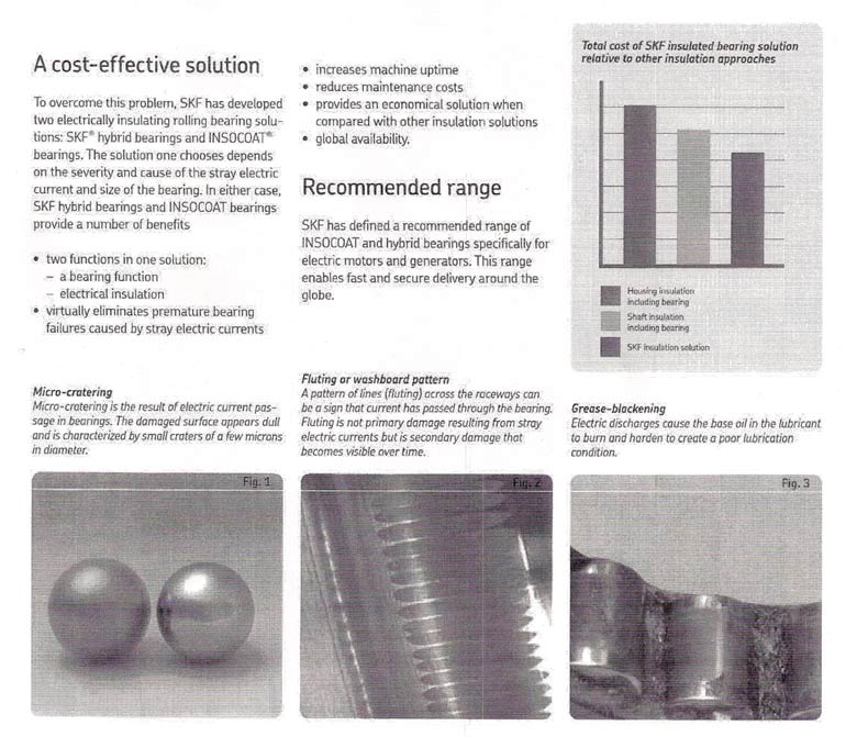
The earliest known in-depth study dealing with EIBD (Electrically Induced Bearing Damage) was completed in 1994 by Hugh Boyanton. His study took six years to complete and involved testing and evaluating data from hundreds of DC and AC motors running on VFD's. The root cause of EIBD was found to be shaft-to-frame voltage or, simply, shaft voltage. Low shaft voltage between 3 to 5 volts is considered normal and, according to motor manufacturers, will not cause a problem with bearings. Using a battery powered digital oscilloscope the shaft to frame voltage on a working motor experiencing EIBD can present ranges from 8 to 19 volts. In some lab tests, voltage spikes can even be in the order of 70 to 370 volts, much higher than what is considered a normal voltage. These high frequency voltage pulses result in capacitive coupled currents which can flow through paths within the motor that are normally considered to be electrical insulators. In systems with a conductive shaft coupling, currents can also flow from the motor through the driven equipment, potentially putting the driven-equipment bearings at risk as well. Over time this current flow through the bearings and the frame causes arcing and pitting in the raceways of the ball bearing, rapid increase in noise and erratic vibrations, higher temperatures, and ultimately, premature failure can occur. Pictures of defective bearing races and roller-balls can be seen on the photo below (Figure 2) and further down on this page (Figures 4, 6, 7, the images under "Control of Bearing Damage Caused by Electrical Currents", the images under "Product Service Bulletin"). The current flow can also result in fluting, which is when material properties in the bearing races are altered through re-hardening after arcing, which is almost as if it has been welded. This creates brittle areas in load zones of the race, which results in fracturing, causing a fluted pattern as shown in Figure 2.
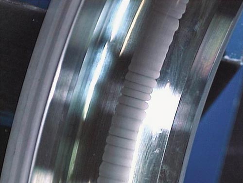
Figure 2: Fluting pattern in an outer bearing race. Vibration levels for the bearing of a motor that is experiencing these defects due to EIBD can be seen on Figures 8, 9, 10, and 11.
Bearing Current Paths
The most common bearing current paths in an inverter-driven motor system are shown in Figure 3.
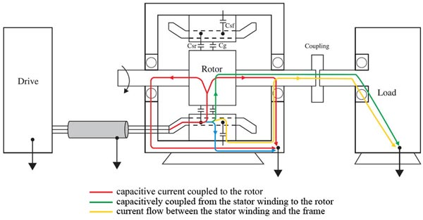
Figure 3: Common bearing current paths in an inverter-driven motor system
The red current path is capacitive current coupled to the rotor, with a return path through the motor bearings, ground connection, and finally to the drive ground. This path is most important in applications where the motor shaft is not electrically connected to a load or where there are no driven-load bearings. The green path in Figure 3 represents current that is capacitively coupled from the stator winding to the rotor with a return path to the drive ground through the driven load. A conductive coupling is required, and the driven load must have its own bearings to support the shaft. The green current flow has the potential to create damage in the load bearing or possibly the coupling itself. The gold current path in Figure 3 represents current flow between the stator winding and the frame. This current flows through the stator winding insulation, which is conductive at high frequencies. With a non-ideal motor to drive high-frequency ground connection, this current flows back to the drive ground through the motor frame, the motor bearing, the motor shaft, the conductive coupling, the load bearing, and the load ground. Current through this path has the potential to damage the motor and load bearings, as well as the motor-to-load coupling. This current only exists if the motor-to-load coupling is electrically conductive.
Conclusions
1. VFD's present in motor applications do cause an induced current on the motor shaft as well as the rotor. Normally in 3-phase motors the sine wave is true and the common mode voltage is zero; but with a VFD, that balance is lost, and the common mode voltage, which is essentially a line voltage, needs to dissipate, so it does this through the motor frame, rotor or the shaft, inducing a current.
2. Motor bearings are not the only things subject to premature failure when experiencing EIBD due to a VFD. If a flexible coupling which connects the motor drive-end shaft to the driven shaft is conductive, a capacitively coupled current may travel down the shaft, damaging the bearings on the driven component and possibly even the coupling itself.
3. Arcing, pitting and fluting are what cause the damage to the bearing due to the current flow through it. The arcing heats up the bearing race or roller-ball material and results in either pitting (which is when the bearings chemical properties change and it condenses, making the roller-balls no longer flush with the inside and outside races), or fluting (which is when the bearing material re-hardens after arcing but now has brittle areas in load zones of the race, which results in fracturing and the fluting pattern).
Recommendations
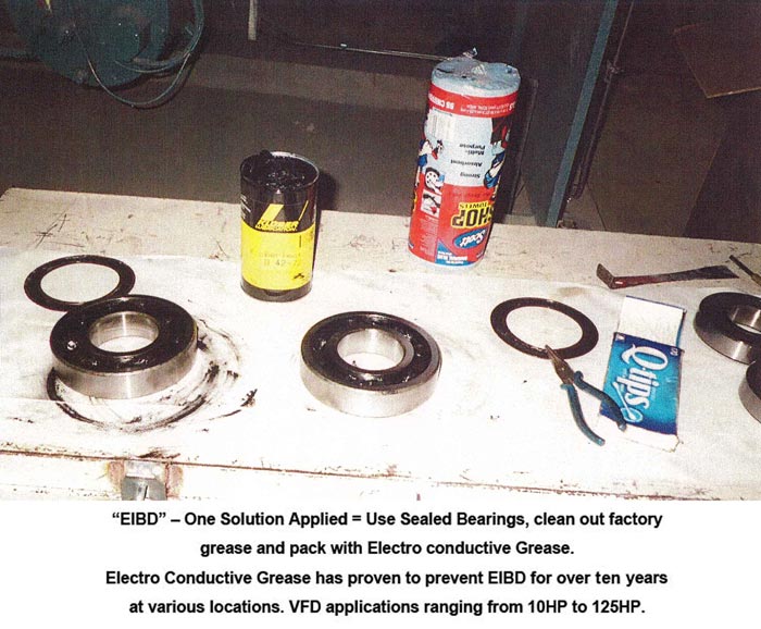
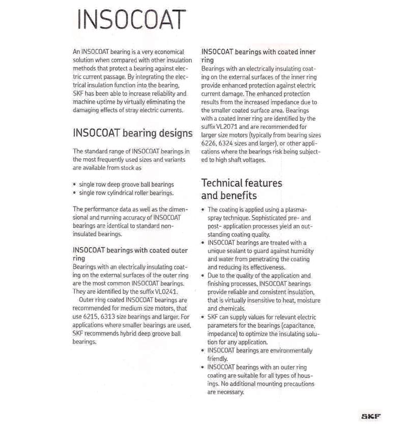
The first (and least costly) solution to combat EIBD is to replace the defective motor ball bearings with new sealed ball bearings that have been cleaned out and repacked with electro conductive grease. The electro conductive grease acts as an insulator and helps prevent or reduce micro arcing through the bearing.
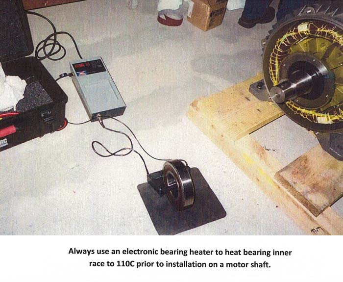
In motors that have a roller bearing in the drive end repack the opposite end (sealed) ball bearing with electro conductive grease. Replacement of the defective motor bearings would require a few hours work depending on motor arrangement in the system. First remove the motor end bells and clean thoroughly. Check the shaft journals for any defects and clean up. Remove seals from the new ball bearing one at a time to clean out the factory grease, then pack the bearing with electro conductive grease about 50% full and install the seals tight. Heat the new motor ball bearings to exactly 110°C then install onto shaft journals. The standard for all new motor bearings inner race is a shrink fit to the shaft. Re-assemble the motor and rotate by hand. If free then run the motor under no load for a few minutes.
This method has been proven to prolong the lifespan of bearings from 5 to 16 years from 10 HP to 125 HP VFD driven motors. Note: Vibes Corp still uses this method when budget is a factor and/or convenience (no other logical solutions) = time issues. There is no knowledge of using electro conductive grease in ball bearings above 125 HP (6318 C3) based on our experience or from any other articles so if considering to do so please confirm or google if it's been done and worked on higher HP motors or larger bearings.
Vibration analysis and bearing noise vs acceleration data can be trusted to trend and confirm if the problem has been solved for a few years and/or when new bearings are required again. Fact: When motor bearings develop shaft current wear damage there will always be a noticeable increase in the noise levels near the motor. When bearings are in serious condition due to shaft current damage it sounds like a skill saw cutting wood.
The second (more costly than the first) solution is to install motor shaft grounding rings or brushes. The motor shaft is grounded with a system of carbon brushes that create a low impedance path to ground that the current will follow – instead of going through the bearings. Two types of motor shaft grounding rings are available:
- External (Shaft Grounding Rings = AEGIS SGR) or (external carbon brush = Baldor SGB) are installed around the shaft and the bracket is fastened to the motor end bell by drilling and tapping holes for mounting bolts. A ground wire should be connected between the seal ring and the stator for best results. The external ring or brush will wear and be subjected to dirt or moisture that will require some maintenance and future replacement.
- Internal (Shaft Grounding Rings = AEGIS SGR) or (Inpro-Seal MGR) are installed at the machine shop. The drive end bell is machined out and a seal ring is pressed in. The internal ring is a better technology, hence more costly than the external ring. It requires more downtime and exact detailed measurements but requires no further maintenance. Note: on some jobs a new end bell was ordered and modified with the internal ring (SGR or MGR) then installed.
The third solution is to install a sine wave filter system. To date this solution has been used on two projects where the EIBD problem was uncontrolled using all other solutions mentioned previously.
The technology using this system is called Inversine Advanced Universal Sine wave Filter. Mr. Tony Hoevenaars, P. Eng. of Mirus International, has kindly offered a few pages of his product technology for this EIBD article (find this information under the header "Resolving Inverter Driven Motor Issues").
The fourth solution, which has been tried with mixed results, is ceramic sleeves to isolate bearings from the shaft or ceramic bearings. Ceramic alternatives are expensive and may have a special application, but according to electrical engineers' feedback from Europe, the rotor must still be grounded on either end. This is due to the fact that, on a large horsepower motor rotor, it could develop much higher voltage if the shaft is not grounded so that arcing between the rotor and stator may occur which could cause an arc flash from rotor to stator thus complete motor failure.
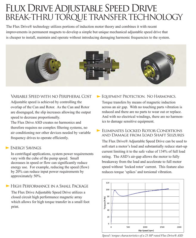
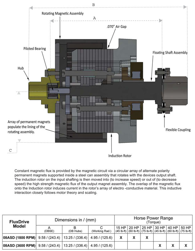
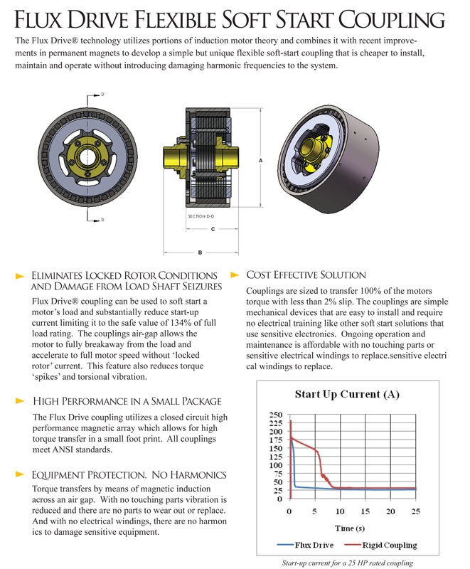
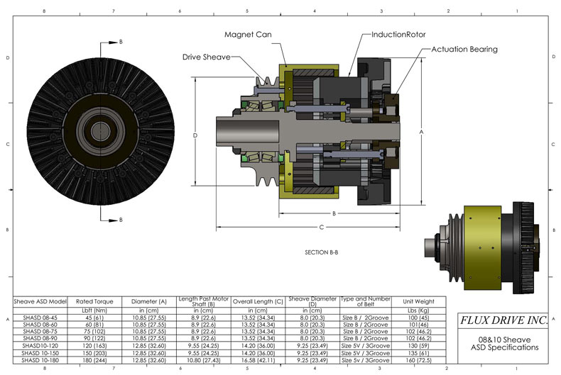
A fifth solution to avoiding shaft currents / EIBD altogether is by converting to Magnetic Adjustable Speed Drives. (Cost to retrofit or covert VFD to ASD may be an issue on smaller HP motors.) This technology has been used at several major facilities in Vancouver, Canada for over 10 years. Our experience and site visits where Fluxdrive ASD are used shows the product and technology are well built and engineered to last. A very popular Vancouver attraction had no other alternatives but Fluxdrive ASD for controlling EIBD/Shaft currents due to the water treatment salt contamination in the spaces and moisture environment where VFD and other solutions would never survive. Fluxdrives are garden or pressure hose washable. Other large ASD or magnetic drive alternatives (couplings) are used on heavy machinery as a soft start or torque control device. Also Google "MagnaDrive". For more detailed information about variable speed magnetic drives see the FLUXDRIVE section of this page.
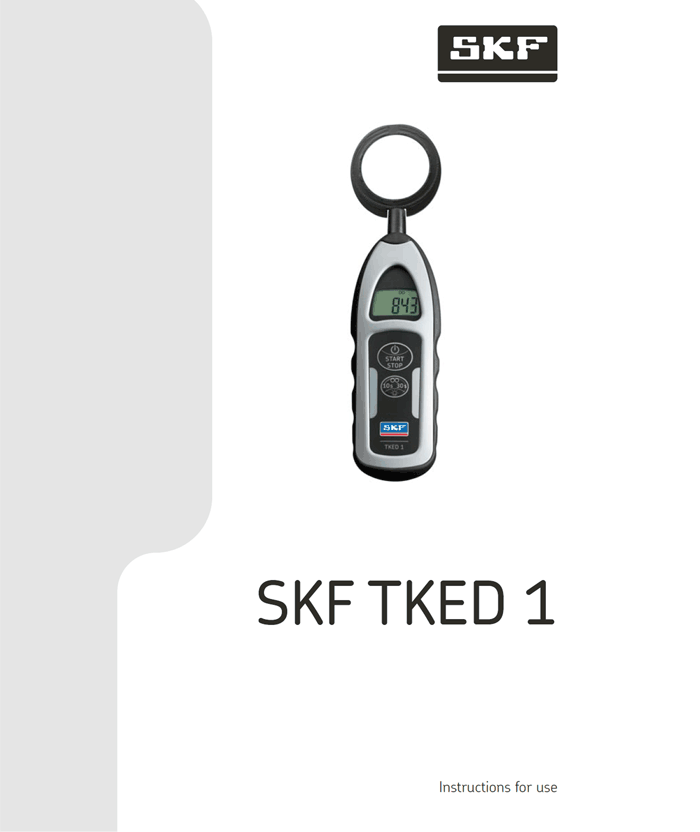
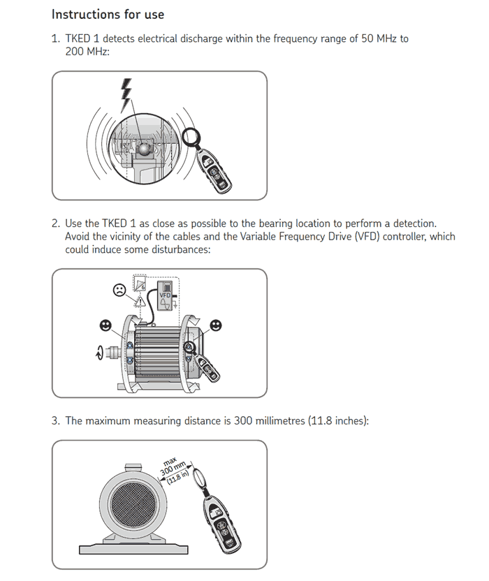
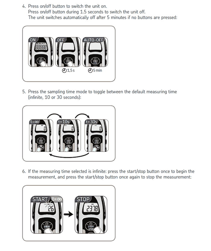
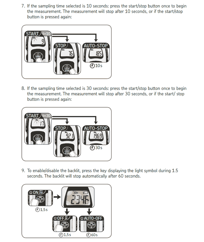
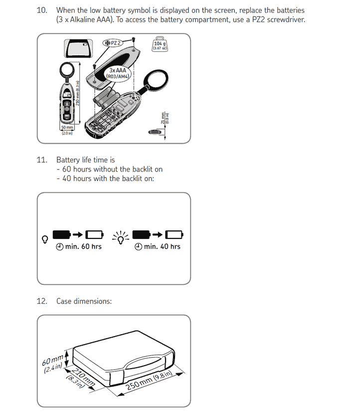
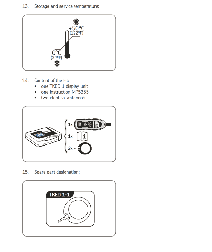
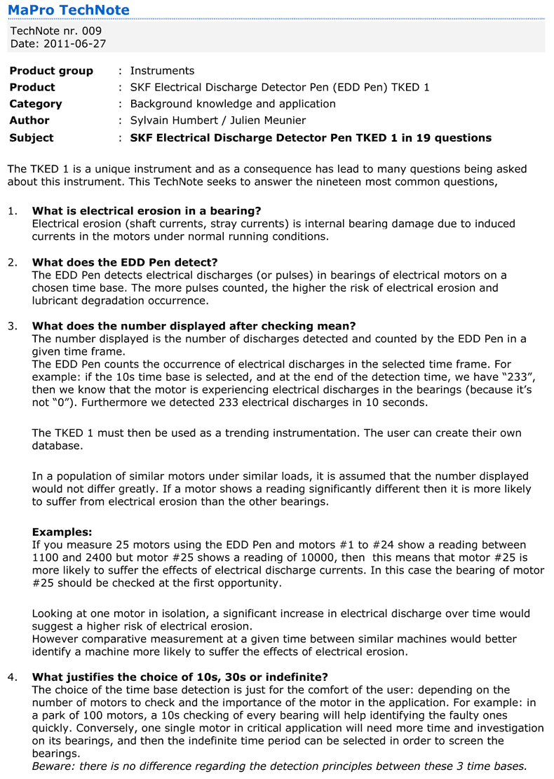
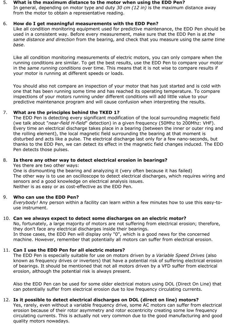
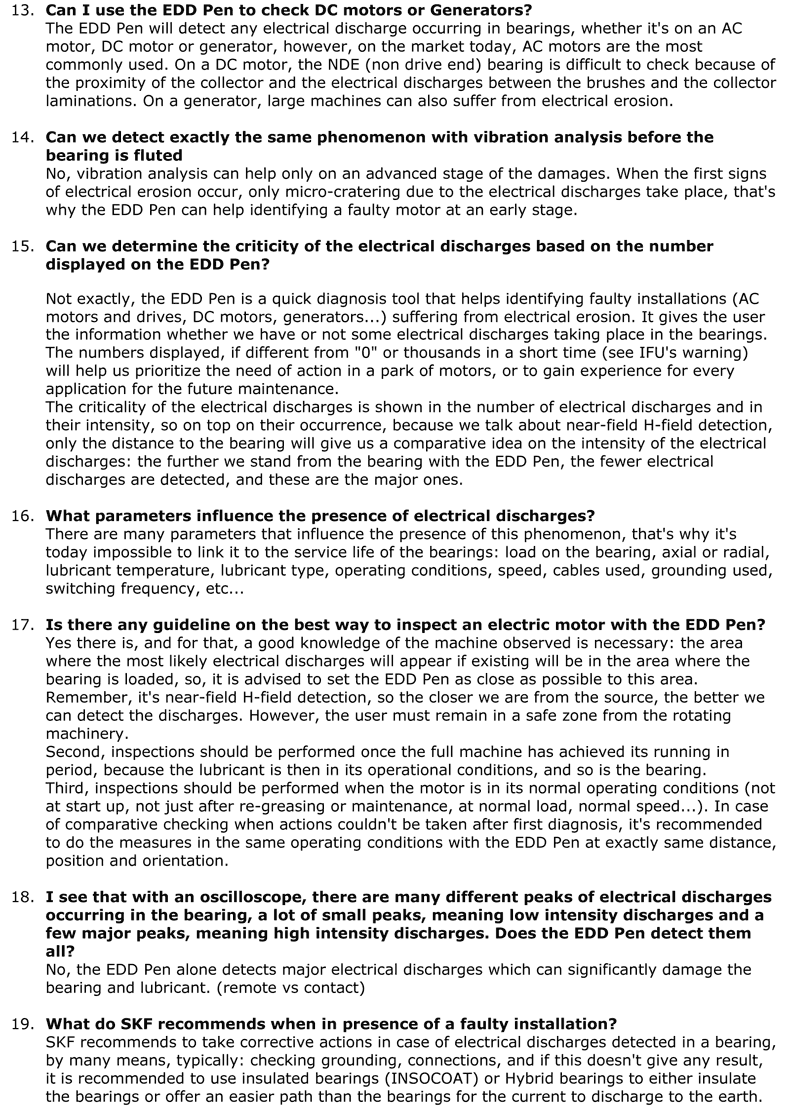
Electrical Discharge Measurement Tool: SKF TKED 1 Meter, Can help you discover if your motor has a problem before costly failures occur. It's called EDD (Electrical Discharge Detector) Pen (Model # TKED 1). This is a tool for detecting electrical discharges (or pulses) and erosion in bearings of electrical motors. It's easy to use and cost-effective. Learn more about this tool in the SKF TKED 1 section of this page, or contact SKF.
See the lists under Figure 15 for various other solutions.
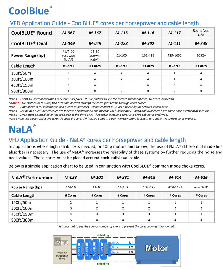
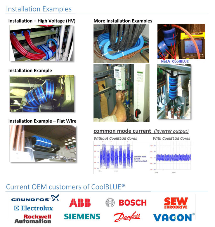
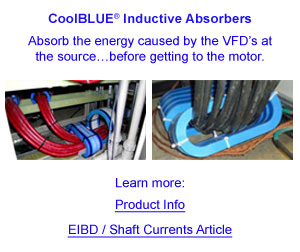
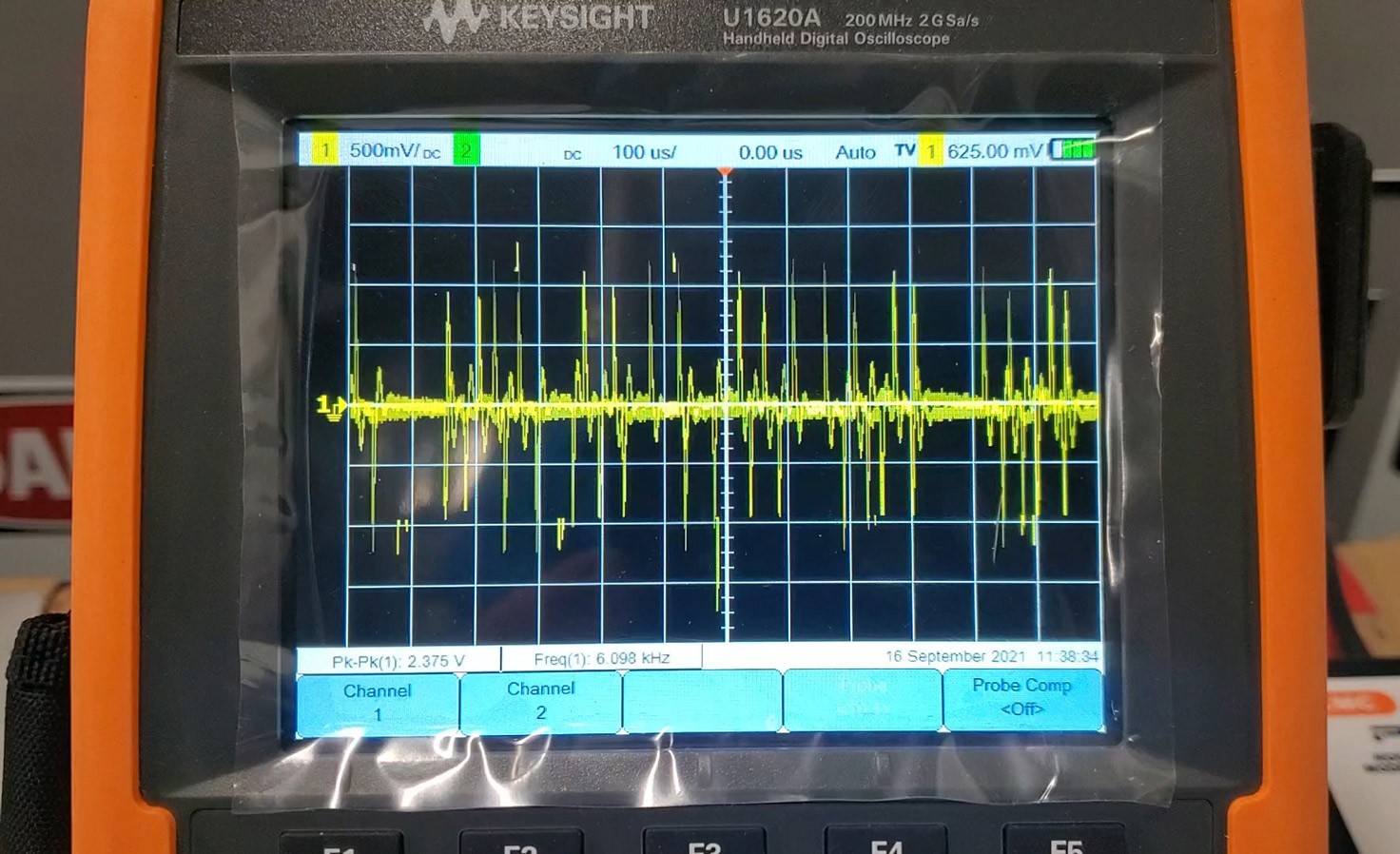
The sixth solution = (on many VFD in Vancouver, Canada) at several facilities has proven smart and very effective where EIBD would have otherwise developed within one year or less. CoolBlue™ products have been installed inside VFD cabinets from 5 HP to 350 HP with excellent results. CoolBlue™ Inductive Absorbers are installed around the three phase wires inside the VFD compartment or a CSA enclosure nearby. The CoolBlue™ technology reduces (harmful) electrical discharge levels (pulses) that travel through the wires to the motor so they don't reach the motors. Note: Electrical discharge levels is the actual main source of shaft current buildup in VFD motors. Rogowski Coil tests (see photos and graphs here) are used before and after installation to confirm electrical discharge levels have been reduced below harmful levels. See the CoolBlue™ section of this page for more information. Also you can review a major CoolBlue™ case study at a Geo Thermal Pump Station here.
Electrically Induced Bearing Damage (EIBD) on a Bearing Race
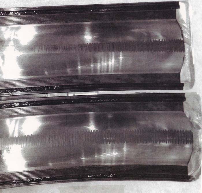
Figure 4: The bearing race shown in this photo was found in the advanced stage of fluting. Vibration spectrum data for this bearing can be reviewed — see Figures 8, 9, 10, and 11. See scanning electron microscope (SEM) images for the above bearing race on Figures 6 and 7.
EIBD / Shaft Current bearing defects have been found at numerous locations on 600Volt (Canada) and 460Volt (USA) VFD motor applications.
Electrically Induced Bearing Damage (EIBD) on a Bearing Race
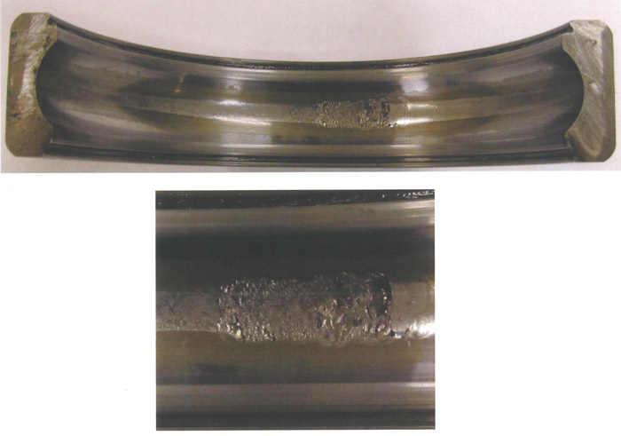
Figure 5: These two photos of the same bearing outer raceway show advanced shaft current / electrically induced bearing damage just prior to failure. Taken September 2011.
Electrically Induced Bearing Damage (EIBD) on a Bearing Race
This SEM image is from Figure 4 bearing race
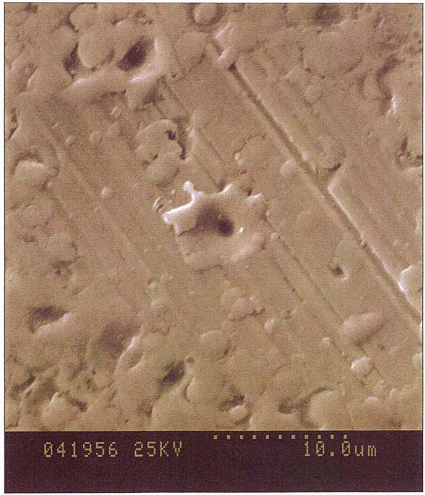
Figure 6: High magnification SEM view of particles flattened onto drive end outer raceway running surface showing variety of particle sizes. Material has clearly been molten at the time of deposit. Magnification 4,500X.
EIBD / Shaft Current bearing defects have been found at numerous locations on 600Volt (Canada) and 460Volt (USA) VFD motor applications.
Electrically Induced Bearing Damage (EIBD) on a Bearing Race
This SEM image is from Figure 4 bearing race
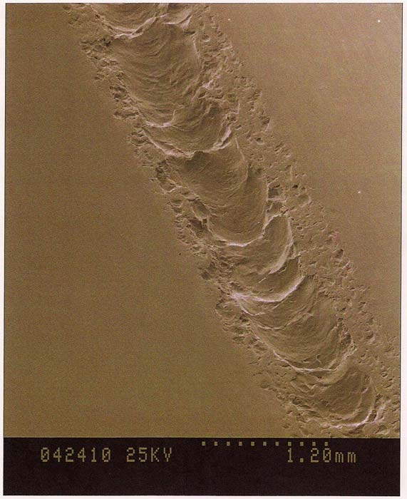
Figure 7: SEM image of the spalling observed on the inside surface of the outer raceway. Magnification 37.5X.
EIBD / Shaft Current bearing defects have been found at numerous locations on 600Volt (Canada) and 460Volt (USA) VFD motor applications.
Electrically Induced Bearing Damage & Shaft Current Issue @ 39 Hz (VFD)
Motor ODE Sensor Location 1. Acceleration g rms High Frequency Range.
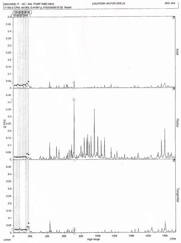
Figure 8: Electrically Induced Bearing Damage @ 39 Hz. The vibration spectrum data shown above was recorded from the bearing (photo) in Figure 4.
Electrically Induced Bearing Damage & Shaft Current Issue @ 39 Hz (VFD)
Motor DE Sensor Location 2. Acceleration g rms High Frequency Range.
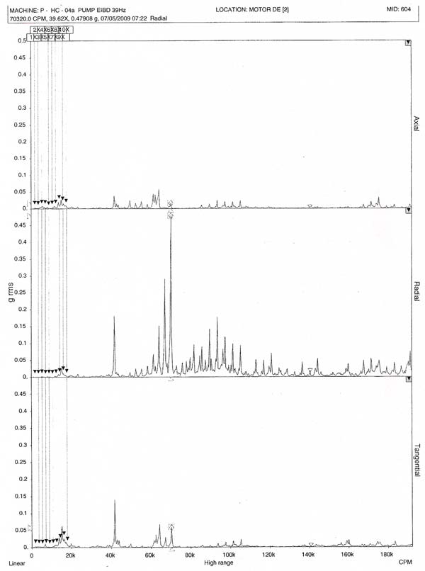
Figure 9: Electrically Induced Bearing Damage @ 39 Hz. The vibration spectrum data shown above was recorded from the bearing (photo) in Figure 4.
Electrically Induced Bearing Damage & Shaft Current Issue @ 60 Hz (VFD)
Motor ODE Sensor Location 1. Acceleration g rms High Frequency Range.
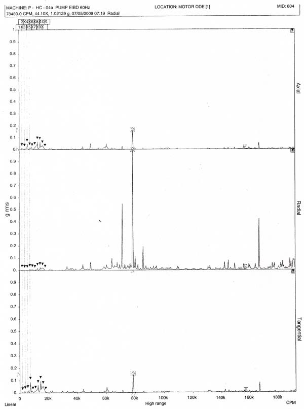
Figure 10: Electrically Induced Bearing Damage @ 60 Hz. The vibration spectrum data shown above was recorded from the bearing (photo) in Figure 4.
Electrically Induced Bearing Damage & Shaft Current Issue @ 60 Hz (VFD)
Motor DE Sensor Location 2. Acceleration g rms High Frequency Range.
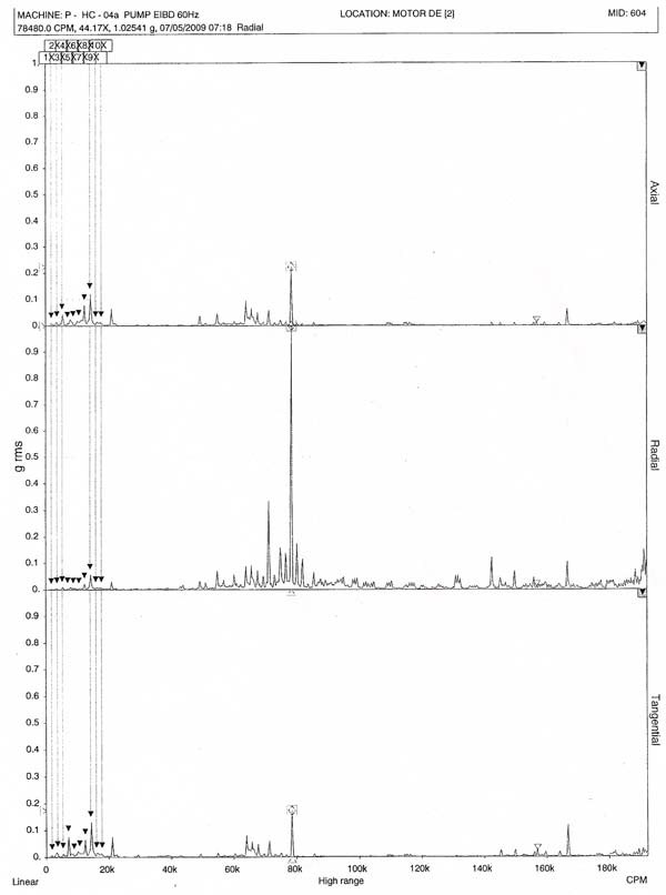
Figure 11: Electrically Induced Bearing Damage @ 60 Hz. The vibration spectrum data shown above was recorded from the bearing (photo) in Figure 4.
Resolving Inverter Driven Motor Issues (Ref: Mirus International Study)
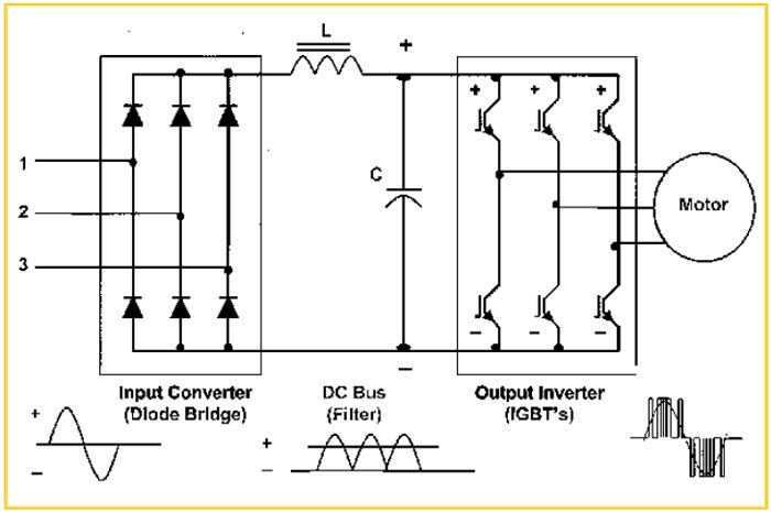
Figure 12: PWM Adjustable Speed Drive Inverters
Adjustable Speed Drives utilize Pulsewidth Modulated (PWM) Inverters equipped with:
- High speed switching insulated gate bipolar transistors
- 2 to 8 kHz switching frequencies typical
- Up to 20 kHz in some small sizes
- Voltage rise (dV/dT) rates of up to 6000 V/μs
Reference: 'An Evaluation of Mitigation Techniques for Bearing Currents, EMI and Overvoltages in ASD Applications', Sept/Oct. 1998
Resolving Inverter Driven Motor Issues (Ref: Mirus International Study)
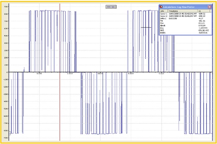
Figure 13: Typical PWM Output Voltage: 600V at 2 kHz
- Voltage rise (dV/dT) = 4400 V/μs
- Peak voltage = 853V
Resolving Inverter Driven Motor Issues (Ref: Mirus International Study)
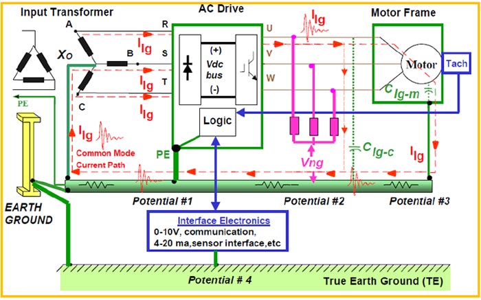
Figure 14: Common-mode Path
- PWM operation produces common-mode voltages
- Common-mode currents flow through parasitic capacitance of cables, motor bearings, etc.
Reference: 'EMI Emissions of Modern PWM AC Drives', IAS Magazine, Nov./Dec. 1999
Resolving Inverter Driven Motor Issues (Ref: Mirus International Study)
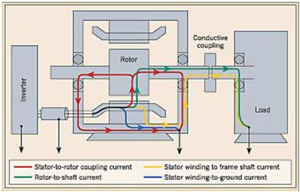
Figure 15: Motor Bearing Currents
Capacitive coupling results in multiple paths for common-mode current
- Stator-to-rotor: Coupled through air gap
- Rotor-to-shaft: Coupled through air gap
- Stator Winding-to-gnd: Coupled through stator winding insulation
- Stator Winding-to-Frame/Shaft: Coupled through stator winding insulation
Methods for Reducing Bearing Currents
- Improve high frequency grounding connection from motor to drive and from motor to driven equipment
- Install one insulated bearing on non-drive end of motor
- Install two insulated bearings on motor
- Install a shaft grounding brush across one motor bearing
- Install a Faraday shielded motor
- Install an insulated coupling between motor and driven equipment, or
- Reduce the common mode voltages
Reference: 'Bearing Current Problems: Causes, Symptoms and Solutions', EC&M Sept. 2005
Resolving Inverter Driven Motor Issues (Ref: Mirus International Study)
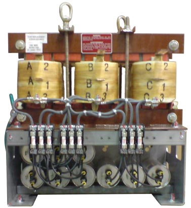
Figure 16: INVERSINE Advanced Universal Sinewave Filter (AUSF)
- Low pass filter with cutoff freq. below switching freq.
- Filters out high frequency currents while allowing lower frequency fundamental currents to pass
- < 3% VTHD
- No damping resistors required
- Cooler operation & much higher efficiency than competitor's filters
- Prevents
- Transient overvoltages at motor
- Additional motor losses
- Excessive motor noise
Resolving Inverter Driven Motor Issues (Ref: Mirus International Study)
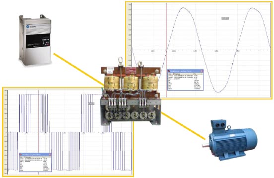
Figure 17: INVERSINE AUSF Performance (Voltage)
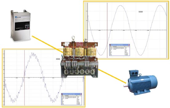
Figure 18: INVERSINE AUSF Performance (Current)
ACTUAL VFD – ROGOWSKI COIL TEST
ELECTRICAL DISCHARGE RECORDED
↑
BEFORE COOLBLUE
ACTUAL VFD – ROGOWSKI COIL TEST
ELECTRICAL DISCHARGE RECORDED
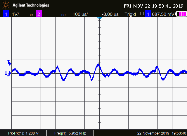
↑
AFTER ADDING COOLBLUE
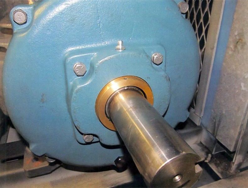
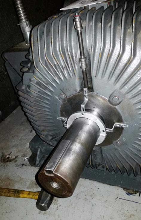
INPRO-SEAL MGS SEAL INSTALLED ON A MOTOR DRIVE END
INPRO-SEAL MGS SEAL INSTALLED ON A MOTOR DRIVE END
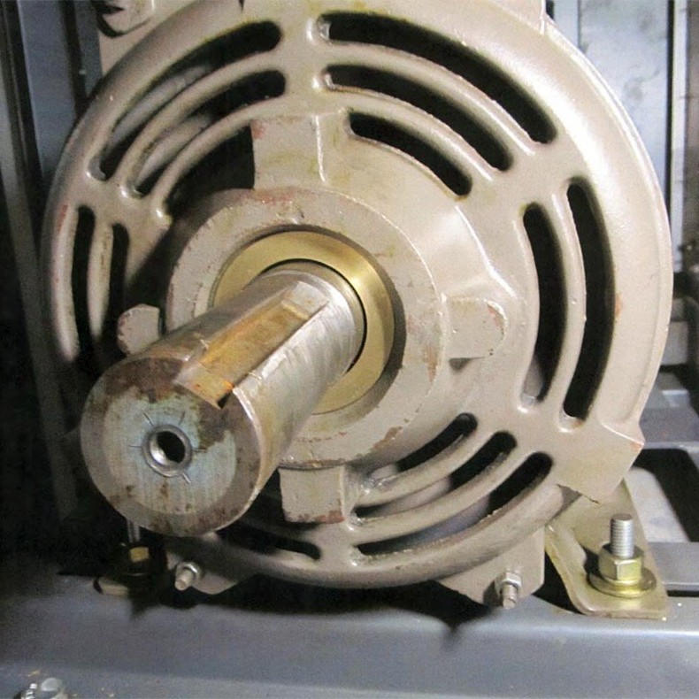
AEGIS SGR SEAL INSTALLED ON A MOTOR DRIVE END
For more information about AEGIS SGR click here
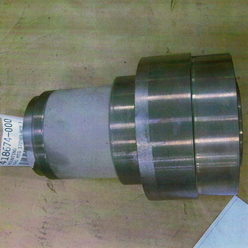
THE PHOTOS ATTACHED ARE AN ACTUAL APPLICATION EXAMPLE OF INSULATING A MOTOR BEARING.
THE INSULATED BEARING AND SHAFT JOURNAL IS ON THE OPPOSITE DRIVE END OF THE MOTOR. NOTE - ON THE SAME MOTOR A GROUNDING SEAL (Inpro-Seal MGS - Photo) WAS ALSO SPECIFIED ON THE DRIVE END.
REFERENCE - Frequently asked questions & answers: www.usmotors.com/default_service.htm 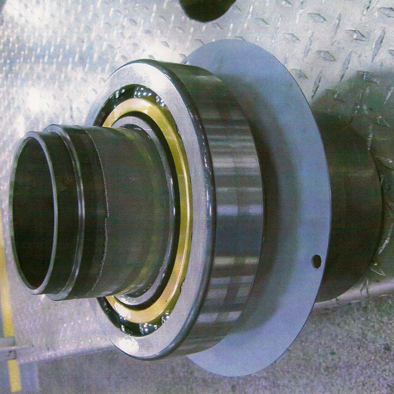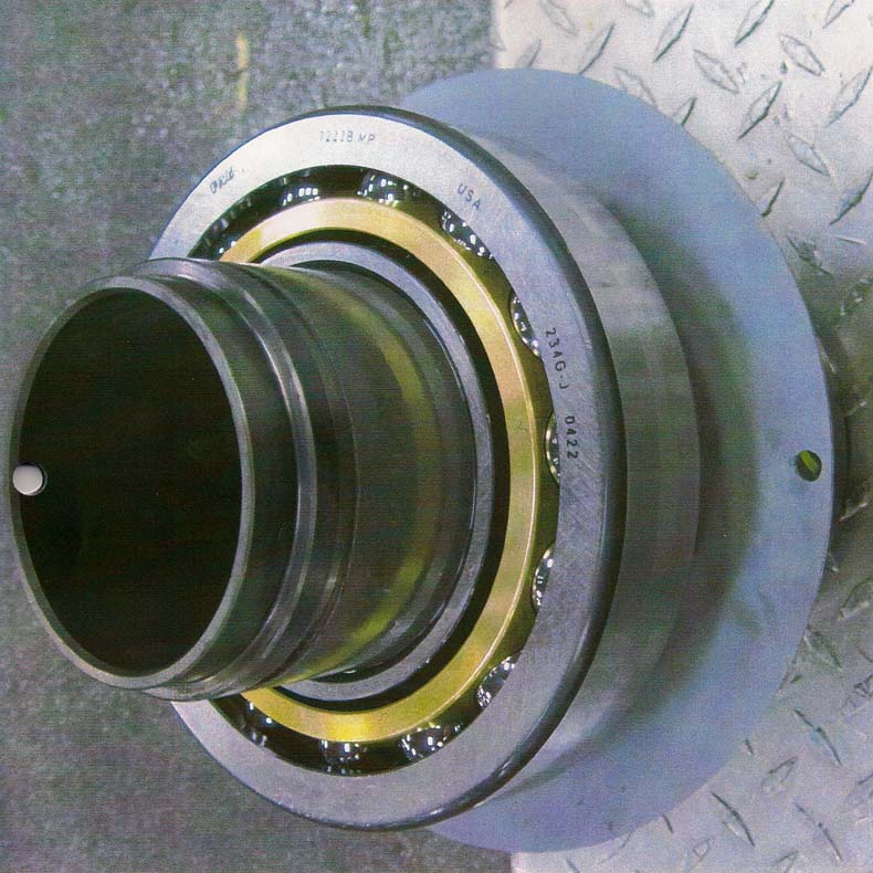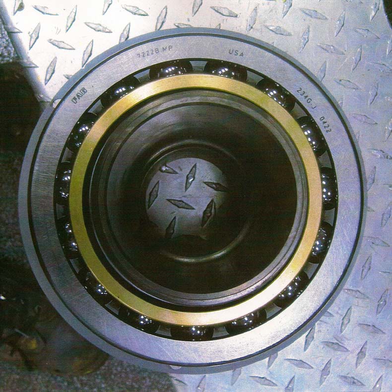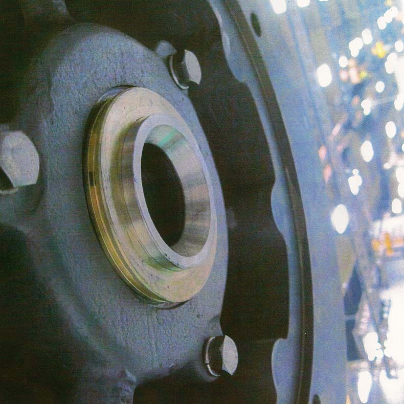
Vibration & Electro-Mechanical Analysis, VIBES-GUARD PDM Program® Service Contracts, On Site - Rotors Dynamic Balancing & Custom Repairs,
Couplings, Pulleys & Drive Shafts Laser Alignment, Rogowski Coil (VFD) Electrical Discharge Tests & Reports.
Sales: WEG Electric Motors, Metalon Synthetic Grease, Cool Blue (Inductive Absorbers), Easy Laser, Wilcoxon / Endaq Vibration & Temperature Monitoring & Protection Products, (Misc) Isolation Springs, Drive Parts & Bearings, Machining, Fabrications, Sheet Metal Projects & Environmental Coatings. Learn About = Free Articles.
|